Week 1
April 4thThe first week of lab was very informative. We learned what our project was, who our partners were going to be, and what is expected of us throughout the term. After the information session, we returned back to our stations and immediately divided up the workload (see Biographies). We then had to to a lot of research to do. The thing we first realized is that none of us have experience in turbine technology, so we had to know how they worked.

Interestingly enough, the mechanism for a wind turbine is not all that complicated. When wind blows higher up in the sky, the blades use their airfoil design (like an airplane wing) to spin at a low speed, relative to the blade length. The blades are connected to a low speed shaft which ends with a large gear. The large gear turns a much smaller gear which is attached to both the high speed shaft and the generator. This gear ratio helps create a much higher yield of electricity. The generator is wired to an electric grid for distribution.

 Also in our research, we learned that the vertical axis wind turbines almost always produce more drag than the traditional horizontal axis turbines, so we decided to go with the traditional design...for now. The last decision we made for Week 1 was what number of blades to put in our design. Every website pointed us in the direction of 3 blades, so once again, that is what we are going with...for now. We're looking forward to Week 2 and conducting our last bit of research before jumping in the Drafting stage of our project. Here is our timeline from our Proposal.
Week 2
April 11th
This week's lab was much more independent. Now that the group knows exactly what the project is and what is expected, we went right to work on brainstorming. The very first thing we were interested in was the gear train involved in the manual transmission of the turbine. Because we need to operate the blade at different speeds, we must have at least 3 speed settings in our manual transmission gear train to allow for control over the wind speed and power production needed. None of us have experience with manual transmission systems, or even how to make them, so we researched home made systems using legos
 Our next focus is on the blade design of the wind turbine. Shape is crucial to capturing the most amount of wind, as it directly contributes to the efficiency of the turbine, which is our main focus. A wind turbine that is up in the air and not capturing the maximum amount of wind is essentially useless and needs to be changed. We do not want this to be the case, therefore, we are still in the research phase of designing the most effective wind turbine blade that will fit to the scale of our project. What we have found is that some sort of twist along the center of the blade adds to drag in which the blade can capture the wing. the edges must also be tapered to create the necessary airfoil and reduce drag. We also need to think about size, as we do not want the blades to be heavy, but we want to capture the most area of wind. It is something that will have to go through much testing. A full scale wind turbine, as can be seen below, uses massive blades to cover the greatest area in the sky. The blades collect more wind to compensate for the inefficiencies within the gear box to produce a generally efficient wind turbine. This rare footage of grounded blades truly shows the scale of the commercially sized wind turbine:
With discussion and research of gear box and blade design, the discussion for CAD renderings of our ideas have begun to happen. Though we still do not have a set design or completed sketches of our wind turbine, the initial CAD drawings will help us visualize spacing and sizing in order to continue drafting our final design. That will be our main focus going into Week 3.
Week 3
April 18th
Our biggest focus this lab was the CAD modeling. We worked on the blade design, the entire assembly of the structure, and most important, the gear box. Although the gear files downloaded successfully onto the lab computers, we could not open them up on our laptops as they were reading as .txt files. Week 4 will definitely have to include resolving that problem so we can complete a gear box mechanism.

We decided that our wing design will be the one from the video in the Background and Tutorial tab. Our plan is to purchase very small diameter PVC pipe and cut out triangles from it. After we trail the edges we still have to be able to connect them all and attach them onto one axis. One idea was to screw them onto a base attached to the spinning rod. We will have to make sure that the rod is as frictionless as possible. Every moving part within our design will have to be lubricated or smooth enough to not need it. In order to maximize efficiency, every loss of energy has to be decreased by a lot, largely including friction.


Week 4
April 25th
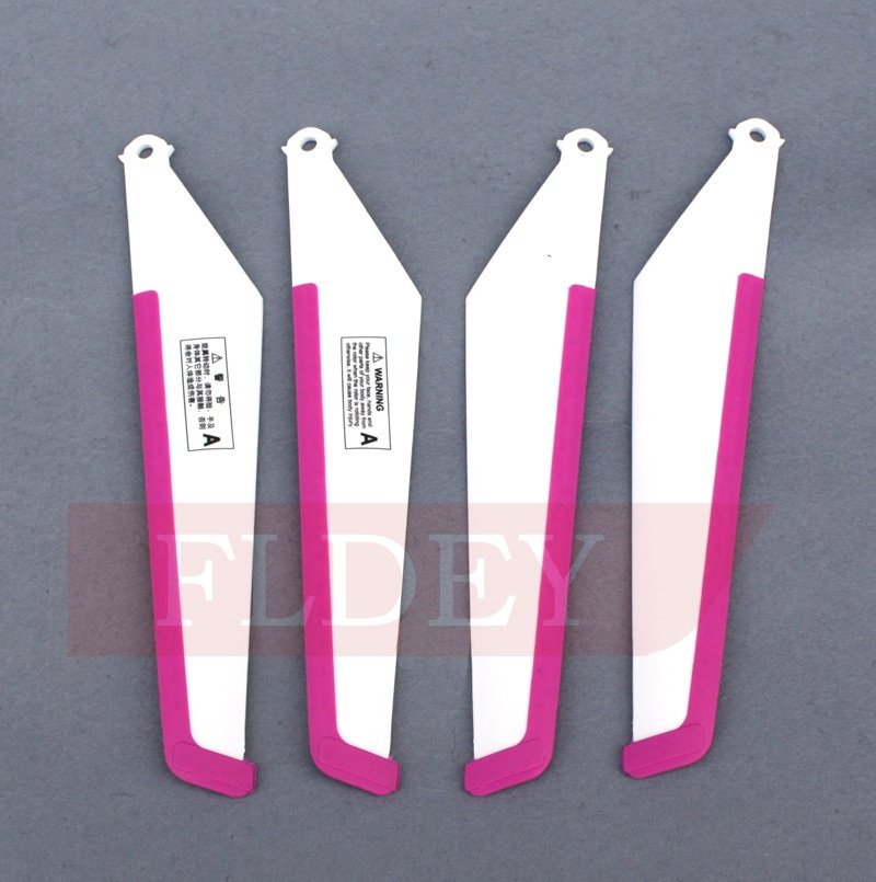 The group has realized that we have to pick up the pace a little bit. We have nothing built and it is already week 5. What must happen today is we must complete our 3D rendering of the gear mechanism and begin work on the rest of the designing. Within the week we have to try and get in the machine shop and start creating a base and blades for the turbine. To do this, we have to all agree on the complete design of the turbine. A thought proposed would be to buy the fan blades from a hobby store if fabricating them may be too much of a hassle. blades to the right are expertly made and inexpensive. Properly made fan blades are crucial to the efficiency of our windmill...if the blades are not properly angled or cut, our design will become terribly inefficient. The group will have to decide on that this week. Another thing that needs to happen is the base. We need to think of a way that we can add small amounts of weight on the bottom to balance out the force from the wind tunnel, this will mast likely be made from wood. We need to work out how the gearbox will sit on the mechanism, and we need to talk t our lab TA's about the files needed to begin printing them out on the 3D printer. While part of the group does the gearbox, the other part will have to do the blades and base. Testing must begin soon, which means the team has to rush through fabrication and assembly in order to get back on track. Hopefully this week's lab sorts everything out and the team can finally agree on designs to begin working with in the machine shops.
Week 5
May 2nd
We are designing the gears in Creo from the website files we were provided. Our idea is to use 1/8" wooden dowels as the shaft for our gears, but the gears first come with circular bores rather than squares. We merely cut a 1/8" square bore into the gear, so it rotates the shaft as it spins:


The rest of the assembly must me modeled in Creo now. The main idea behind our design is simpleness yet efficient. We start with an empty wooden box as the base to allow us to add in any sort of weight to hold it down. Two long thin pieces of acrylic will attach to the gear box and serve as the spine of the windmill. The blade and DC motor will be attached at their respective ends, and the assembly may or may not need a windscreen for the gearbox. That will be determined later.

So far, the Creo model is coming along nicely. We are still working out the exact distance to place the gears, where to put the DC motor, and what kind of fans we are having (whether or not we buy them or make them). However, this is the overall layout of our windmill and it most likely will not change. We will update it more during this weeks lab.
Week 6
May 9th
This week was mainly Creo designing and looking up what kind of materials to use. Some crucial decisions were made during today's lab. To start, we decided that too much wind will be getting into the gear box and it could cause a potential shift of the gears on its own. We do not want the wind affecting anything but the fan blades we we decided that we are going to place a long cardboard tube over top of the entire model, only allowing for the blades to be exposed. We have yet to test it as we still have to assemble our model and purchase our tube, but we feel like it is an idea that will save the project from failure.
The gear box design we chose is proving to be a great choice so far. We have only had to send two sizes of gears to the 3D printer, which is much easier to keep track of. We have not gotten our gears back yet, but we do know the calculations of our gear ratios:
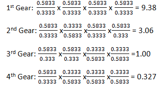
The estimated numbers we were given in lab was that the lowest fan speed found was 563rpm , and on the third wind tunnel speed setting, the fan speed was found to be 2100rpm. The operational speed for the DC motor shaft is 5800rpm. With these gear ratios, we will definitely be able to achieve this speed by either speeding up or slowig down the motors, depending on how fast the wind is blowing at the fans.
We also decided what we needed to order for Week 7. We need sheets of acrylic and L brackets to made the braces and box of the base. We need square dowels and round towels to fit to both the gear bores and the round holes drilled into the brackets. We need small plastic piping to make our own fan blades with. If this does not work, thick fan blades printed out of the 3D printer is the second option for that. We are also printing out the gears and the brackets, since the gear box must be perfect in order to function. We will see what materials we can find and how the gears printed out for next week's lab.
Week 7
May 16th
This week lab was two steps forward and one step back. To start, we found all of the materials we needed. For the box, we found some relatively strong, clear acrylic that will be a good base for the windmill to stand on. It is easy to drill through so the L-brackets we found will also work well in creating the box. We also found some very strong sheets of ABS plastic, that can be used for the braces of the design as well as possible fan blade designs if we have to use that option. 1/2" plastic pipes were purchased to see if we can make custom made fan blades. We found square walnut dowels and round wooden dowels to be used as our shafts, but this is where the problem started. The alleged "1/8" inch square walnut dowels were actually about .186" along each side, which we found using the digital caliper. The squares we ordered to be cut out of the gears were 1/8" each, which work perfectly with the round dowels. Also, the 3D printer printed out a circle inside of each small gear rather than a large gear. Not only did we need to fix the bores cut into the gear, but the gears themselves were not chosen correctly. We chose gears that did not have the same diametral pitch pr pressure angle. Now, we have chosen a .5833" and a 0.3333" gears that have diametral pitches of 48 and a pressure angle of 20 degrees. Compared to the last 3D model of the gears, it is easy to see that these mesh way better:


The last thing we did in lab, after we hurdled the gear obstacle, was a 3D model of the entire design. Since we have not worked out exactly how the square/round shaft system is going to work yet, nor where we are going to place the DC motor, we created everything we did know into a final rendering:

Between this lab and next week's lab, we have to go to the machine shop and finally assemble all of the parts. We have to order the extra parts to the 3D printer and we also have to begin shaping our fan blades. Definitely a lot of catching up to do between these weeks but we knew obstacles would arise at some point.
Week 8
May 23rd
 This week we received our first parts from the 3D printer. The plastic was much harder than we thought, so the small gears we chose are no longer a concern in breaking. Though the diameters were perfect, the pressure angle was off. The large gears pressure angle was 14.5 degrees, while the small gears pressure angle was 20 degrees. The two gears did not mesh well together. Also, the bore within the gears was too small for the square dowels we bought. However, the small gear proved to be too small for the 3D printer to cut out the square in it, so what it printed out was a circle. Our plan was to use square dowels, so we could not use these gears.
 We were able to print out a new set of gears with the correct pressure angle of 20 degrees in each. We had to alter the sizes of each gear, and we thought that the small gear increasing in size would help the 3D printer be able bore a square in the small gear. Without being able to print out any any more gears, we have to use the smaller round dowels as our shafts. In the picture below, it is easy to see that the gears mesh a lot better in the new gears.


 This week we have received our last parts needed to complete the assembly. The 3D printer made the braces to contain the gearbox. The holes in each brace are separated just enough to fit the gears together perfectly. The idea is to use wood to give the gear box some height so it is directly in the middle of the air stream created by the wind tunnel. We glued the braces to the wooden brackets that are attached to the plywood base. We glued the gears to the shafts and constructed the gearbox.


 Everything fits together perfectly, and the height and size will fit in the tunnel. The gearbox, however, is not yet working. The gears and shafts did not glue together perfectly centered, so the rotation is more of an oval than a circle. This makes the gears mesh too tight and too lose, and the gearbox simply does not work. These are the only gears we have, so in order to make it work at all, we have to change the bracket's hole distances. With a drill press that is hard to created the perfect placed holes, this could be quite a challenge. We did however get a break with the motor. The small gears slides tightly on top of the gear on the motor and makes a perfect 1:1 ratio, un-affecting the original ratios.
Week 8
May 23rd
 This week we received our first parts from the 3D printer. The plastic was much harder than we thought, so the small gears we chose are no longer a concern in breaking. Though the diameters were perfect, the pressure angle was off. The large gears pressure angle was 14.5 degrees, while the small gears pressure angle was 20 degrees. The two gears did not mesh well together. Also, the bore within the gears was too small for the square dowels we bought. However, the small gear proved to be too small for the 3D printer to cut out the square in it, so what it printed out was a circle. Our plan was to use square dowels, so we could not use these gears.

We will see how well the shafts and gears work together. We are concerned that the gears will be off centered because the bore size and shaft size, which will make the linear gear system not correctly aligned. This could cause problems, so we will see how it turns out next week.

We have also received fan blades and a hub. After gluing the three blades to the hub, we see that the blades are definitely smaller than we thought it would be. Hopefully the fan blades prove to be designed well enough to compensate for their design. We will test the fan blades next week, and begin construction and assembly. We have also sent the rest of the parts to the 3D printer to make the entire structure next week.
Week 9
May 30th
 This week we have received our last parts needed to complete the assembly. The 3D printer made the braces to contain the gearbox. The holes in each brace are separated just enough to fit the gears together perfectly. The idea is to use wood to give the gear box some height so it is directly in the middle of the air stream created by the wind tunnel. We glued the braces to the wooden brackets that are attached to the plywood base. We glued the gears to the shafts and constructed the gearbox.


 Everything fits together perfectly, and the height and size will fit in the tunnel. The gearbox, however, is not yet working. The gears and shafts did not glue together perfectly centered, so the rotation is more of an oval than a circle. This makes the gears mesh too tight and too lose, and the gearbox simply does not work. These are the only gears we have, so in order to make it work at all, we have to change the bracket's hole distances. With a drill press that is hard to created the perfect placed holes, this could be quite a challenge. We did however get a break with the motor. The small gears slides tightly on top of the gear on the motor and makes a perfect 1:1 ratio, un-affecting the original ratios.
We finally found success! The fan blade works perfectly. If we can figure out the gearbox our design will be complete. Hopefully by week 10 the entire design will be completed.